Pictures
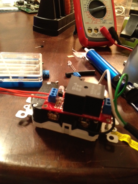 This is a prototype of the relay switch when we were first
trying to figure out how to control the outlets. This prototype included a relay control kit
purchased from Sparkfun.
This is a prototype of the relay switch when we were first
trying to figure out how to control the outlets. This prototype included a relay control kit
purchased from Sparkfun.
 Originally we used an Arduino shield to test and program the Xbee modules.
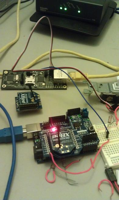
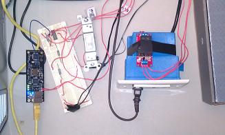 This is a prototype setup that we built for testing using a breadboard, the spinneret webserver, and the sparkfun relay kit.
![]() This is an empty PCB board we designed with the help of the ExpressPCB company.
This is an empty PCB board we designed with the help of the ExpressPCB company.
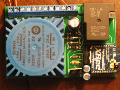 Here we have the PCB board fully populated and soldered with all the components.
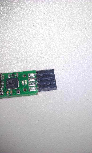 This is a USB propgrammer used in programming the spinneret web server.
 This is the spinneret web server with the xbee module connected.
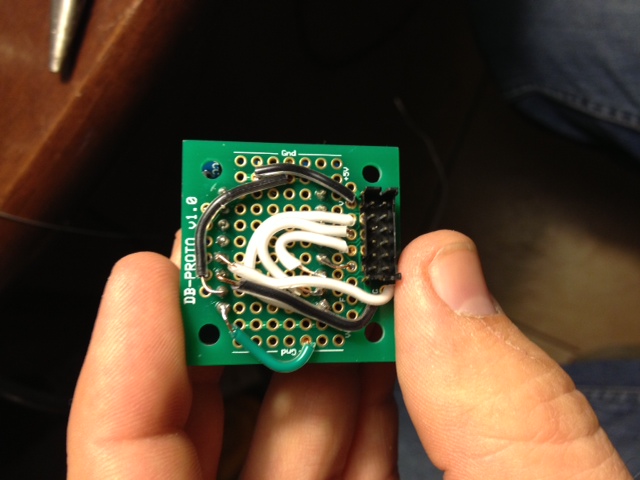 This is the underside of the XBee module with some soldering work we did to connect the spinneret to the Xbee adapter.
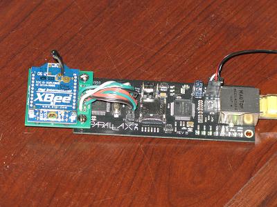
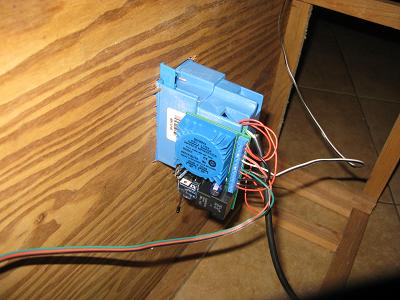
 This is a side view of the spinneret web server.
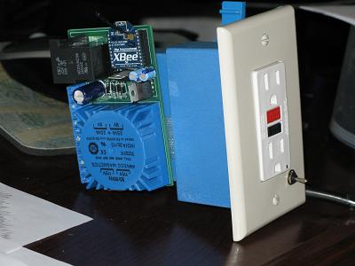
 Here is the final outlet module from the front view.
education at a later date.
Here is the final outlet module from the front view.
education at a later date.
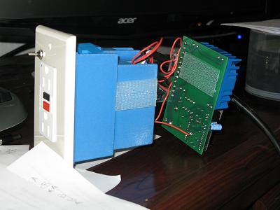
 This is the outlet module from a side view.
 This shows how the PCB can be attached and detached from the power outlet using velcro.
 Here is one of the modules connected to a demonstration deisplay to show what it would look like mounted in a wall. The top left sensor is a door sensor, and the top right is a motion sensor.
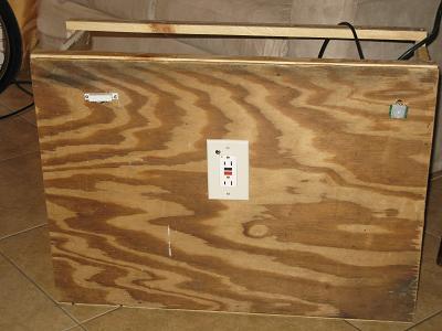
 This is a rear view of the demonstration display.
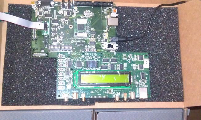 Here is a picture of the OMAP processor and development board loaned to us from Alcorn-Mcbride.