Home | Background | Design | Documents | Multimedia | Team Profile
|
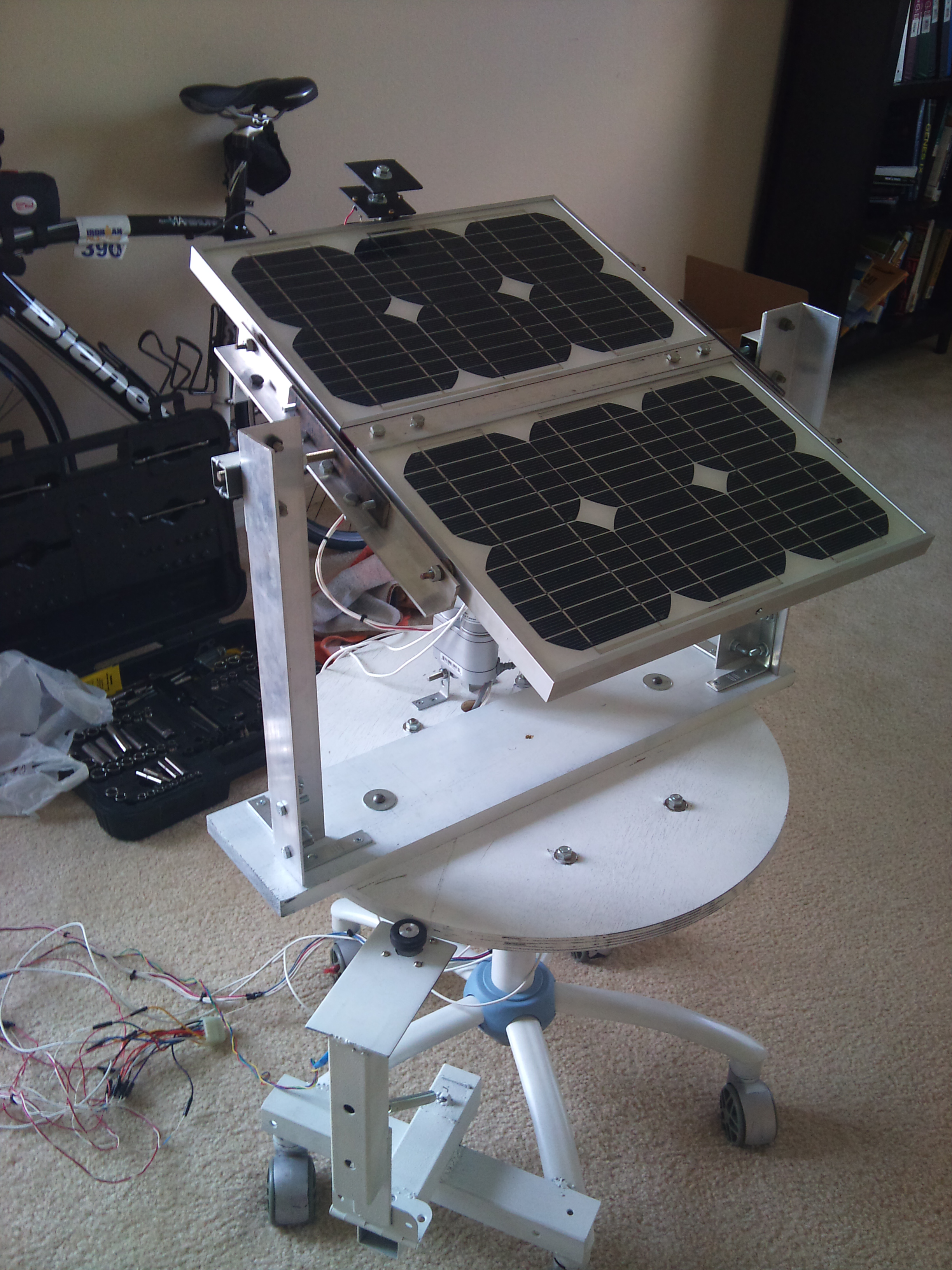
This picture represents the final S.E.G.S. Design | |
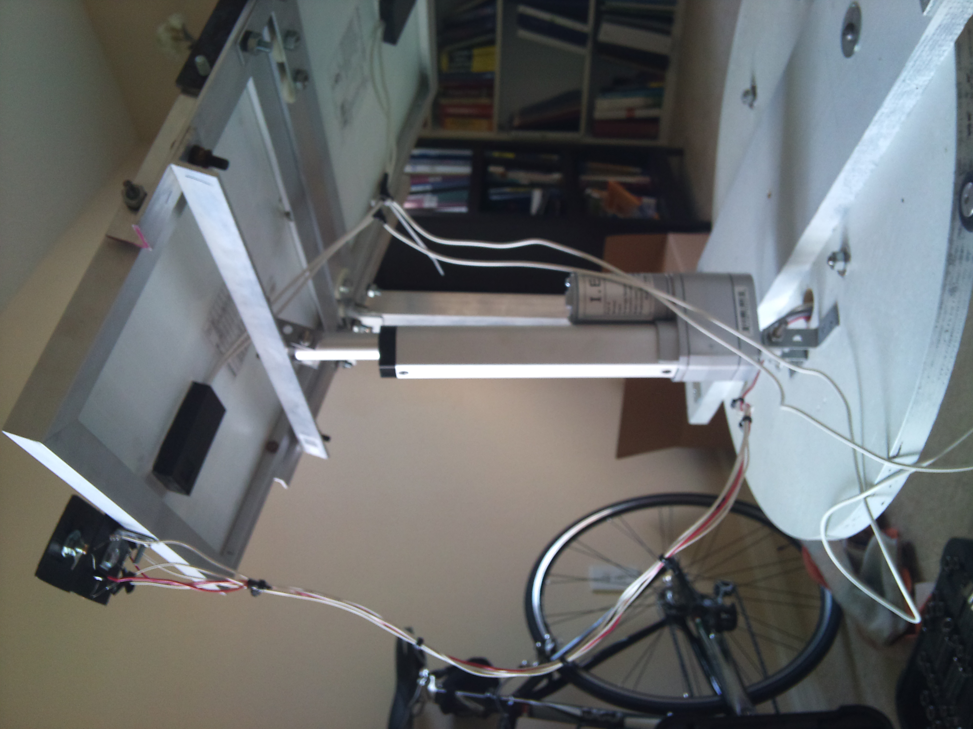
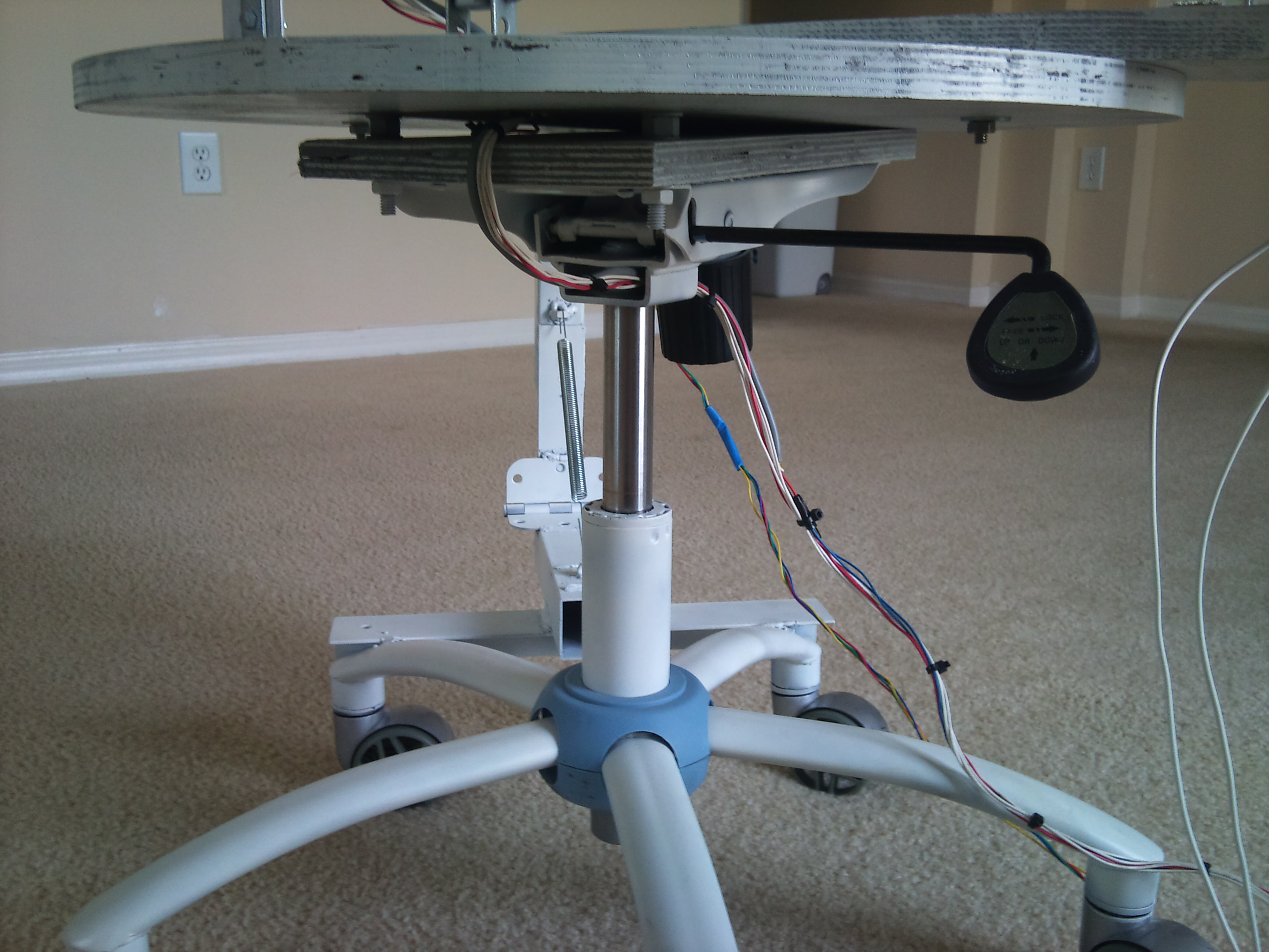
This picture represents the Linear Actuator on the S.E.G.S. Design | |
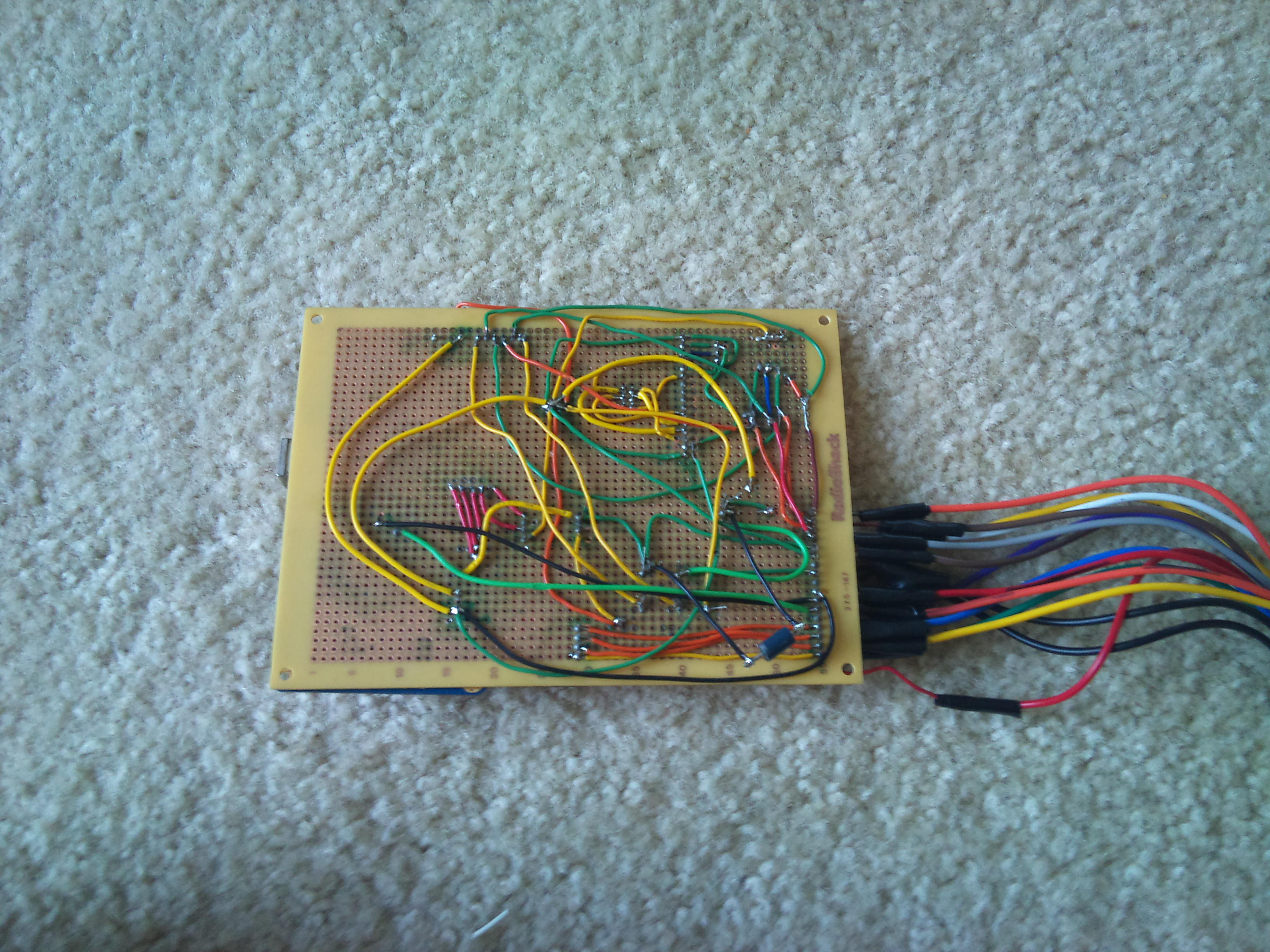
This picture represents the final PCB Design on a Perf Board. | |
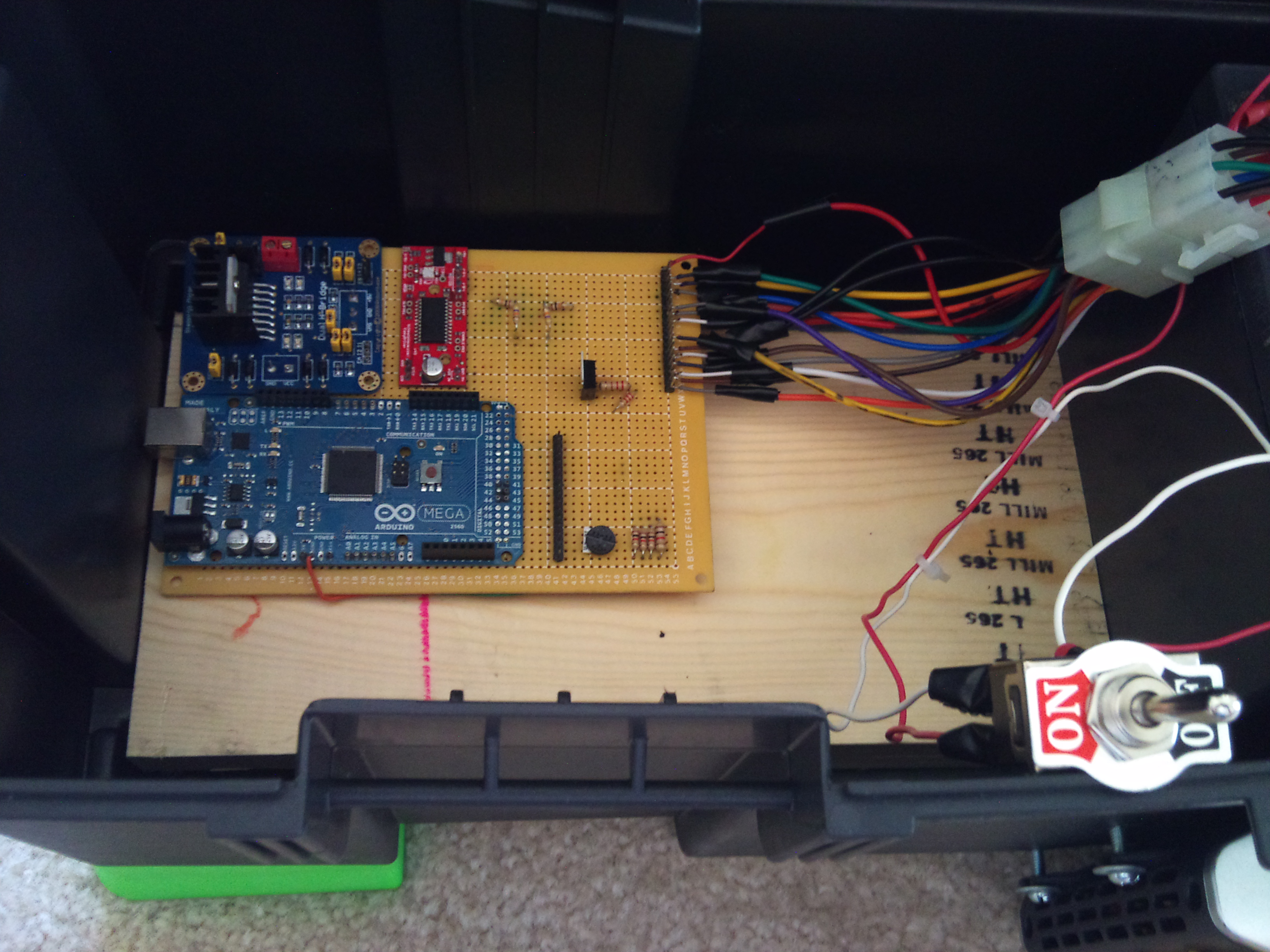
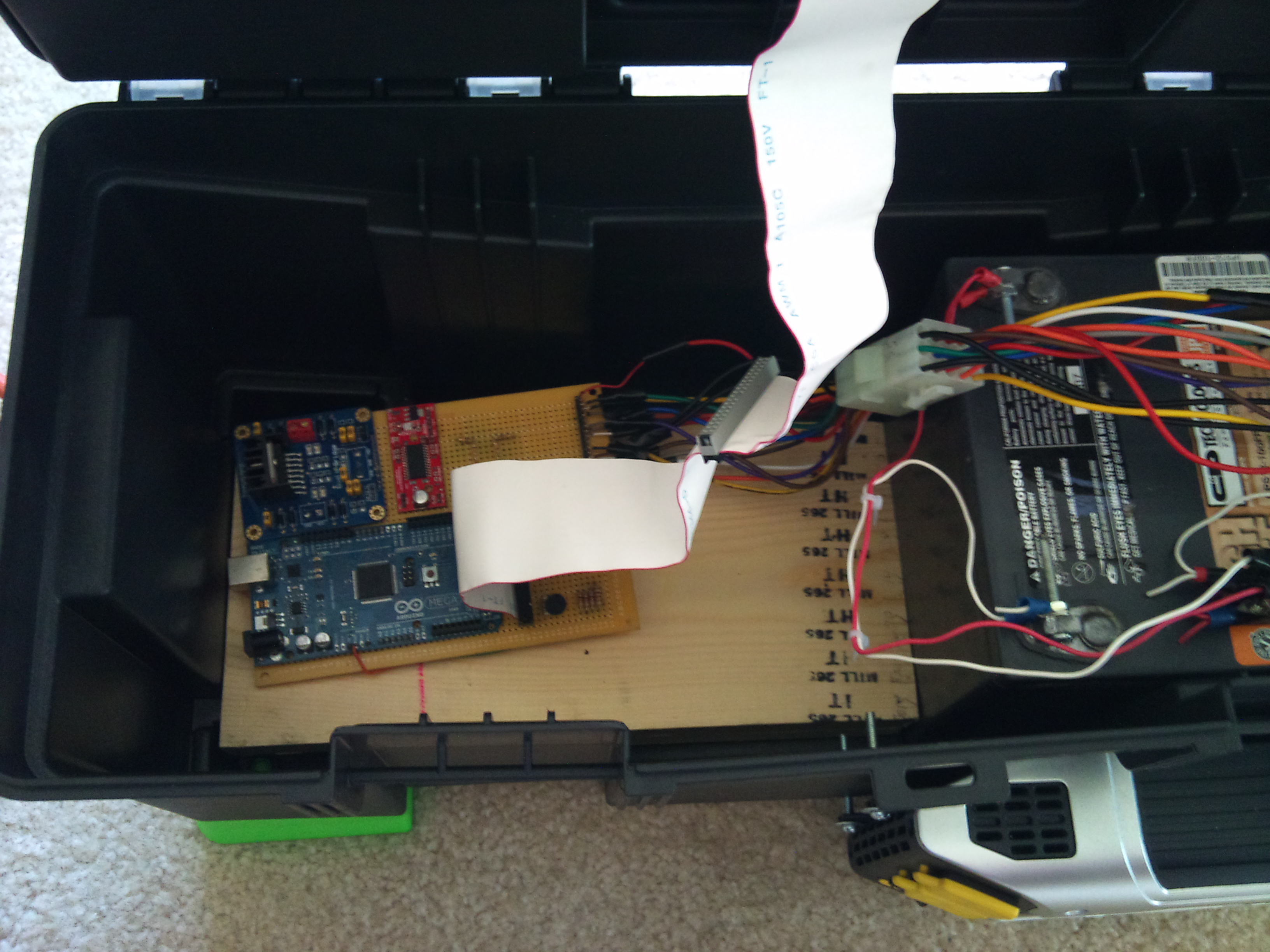
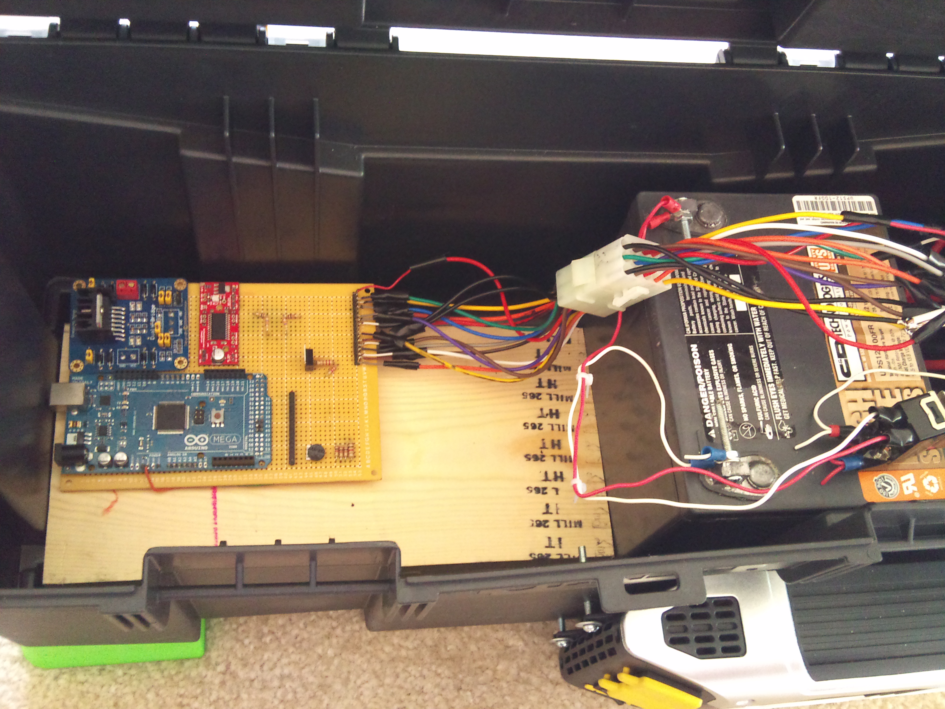
This picture represents the final PCB Design on a Perf Board inside of the electronics case. It is also possible to see the power switch used to allow or restrain power from the battery. | |
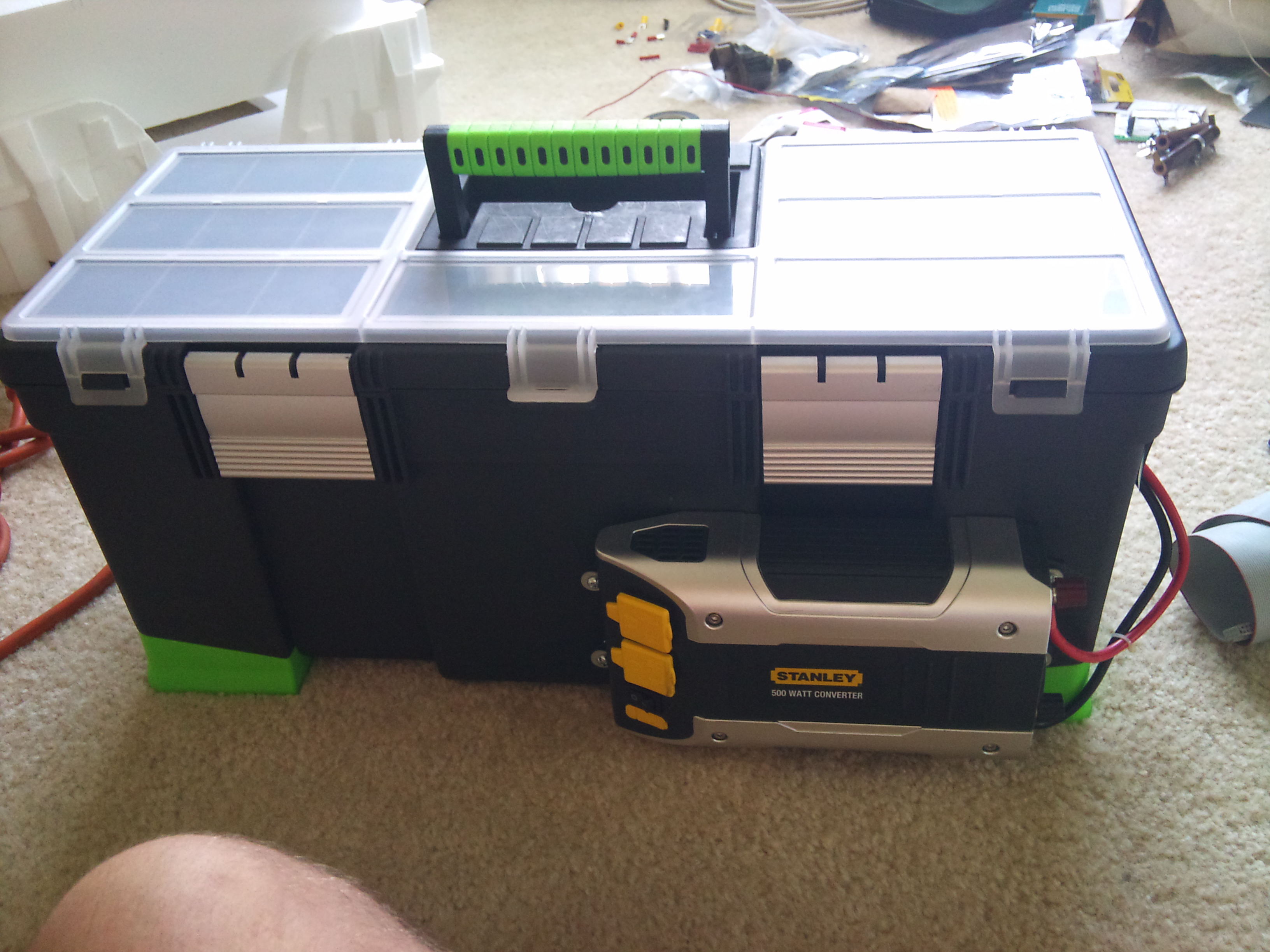
This picture represents the outside view of the electronics case. It is also possible to see the power inverter on the front right hand side. | |
This picture represents the wiring from the panels and motors. Using this design when the tracker rotates, the cords do not become tangled. | |
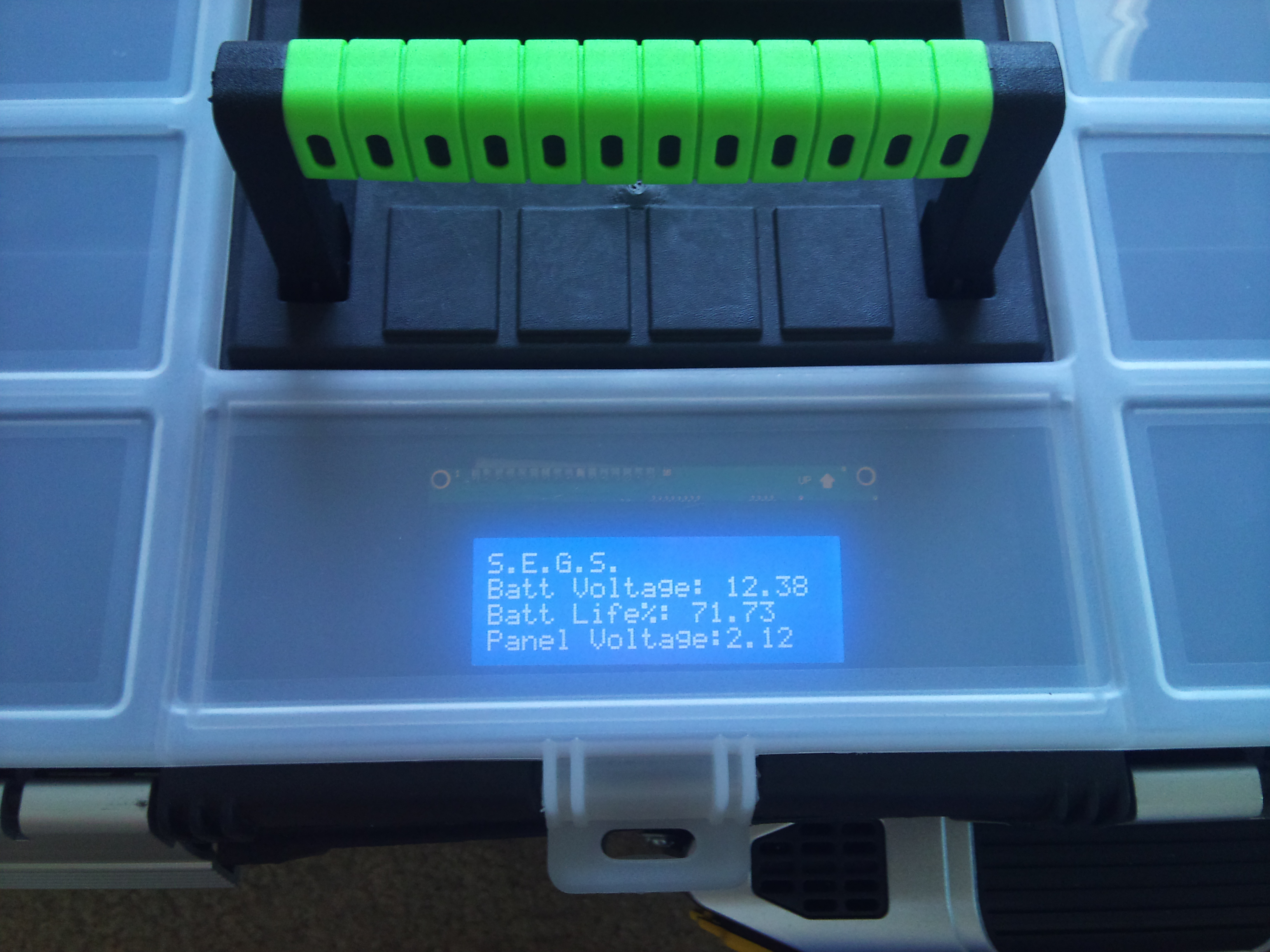
This picture represents the Hitachi HD44780 LCD display in its housing on top of the electronics case with the protective covering.This covering can provide protection from the outdoor elements. | |
This picture represents the ribbon cable connection from the Perf Board to the Hitachi HD44780 LCD Display. | |
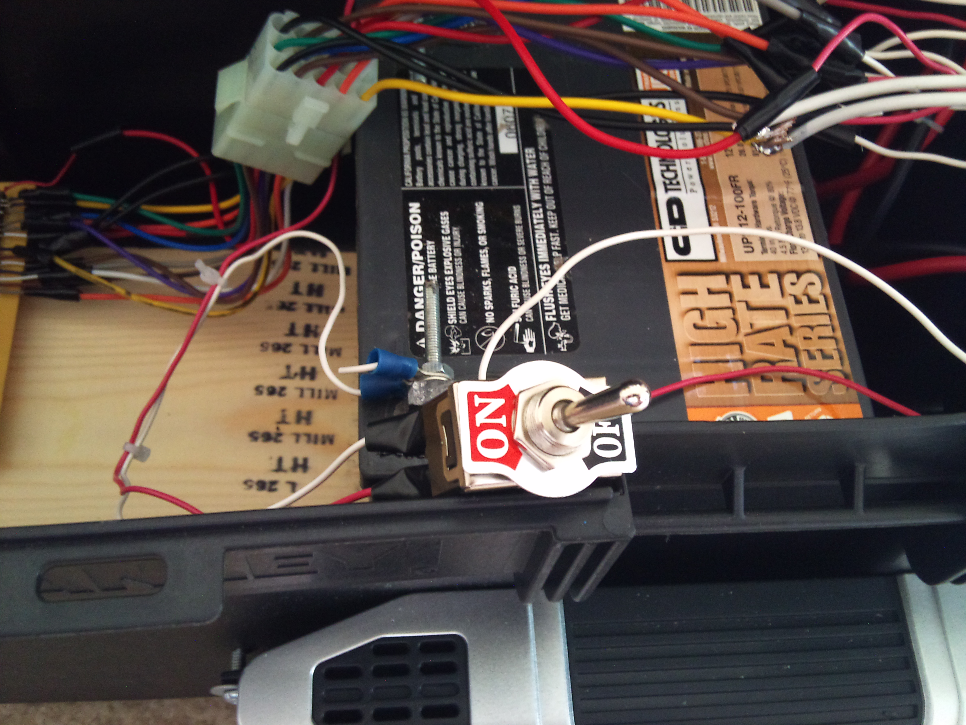
This picture represents the switch used to allow or restrict power from the battery to the other components of the circuit. | |
This picture represents the final PCB Perfboard Design, the 12V Lead Acid Battery, and corresponding wires all properly housed in the electronics case. |