Objectives
- To verify Ohm’s Law experimentally.
- To understand the concept of power absorption and delivery associated with electrical elements.
- To observe conservation of energy in a circuit.
- To understand the power rating of a resistor.
- To understand the Constant Voltage and Constant Current modes in DC Power Supply.
- To familiarize with taking voltage and current measurements using a DMM.
Equipment
- Breadboard
- DC Power Supply
- Digital Multimeter (DMM)
Background
I. Ohm’s Law
Under constant temperature condition, the voltage \color{black}V between two points in a circuit is linearly proportional to the current \color{black}I that flows from one point to the other, \color{black}V \propto I. The proportionality constant, denoted by \color{black}R, is the resistance between the two points considered. When Ohm’s Law is applied, passive sign convention must be taken into account, as shown in Figure 2 – 1.
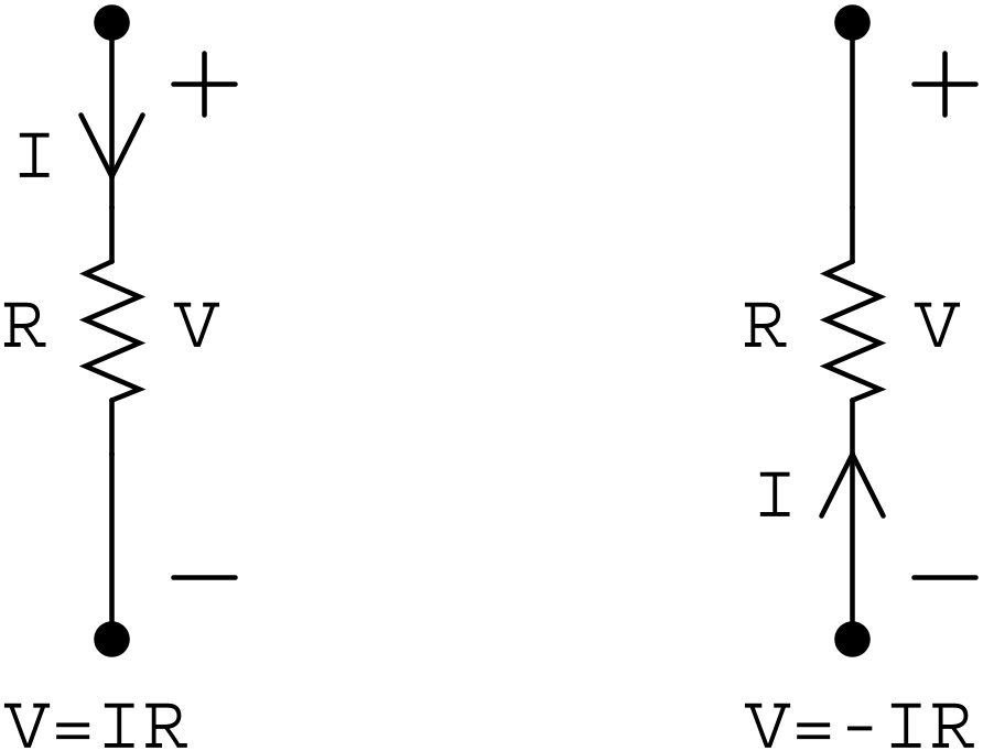
Figure 2 – 1 Ohm’s Law with Passive Sign Convention
II. Conservation of Energy
The power absorbed or delivered by an electrical element is associated with the flow of charge and follows directly the definitions of voltage and current. The power \color{black}P associated with an element is simply the product of the voltage \color{black}V across the element and the current \color{black}i that flows through the element, \color{black}P = Vi. Similar to the application of Ohm’s Law, passive sign convention must be considered when power calculation is performed, as shown in Figure 2 – 2.
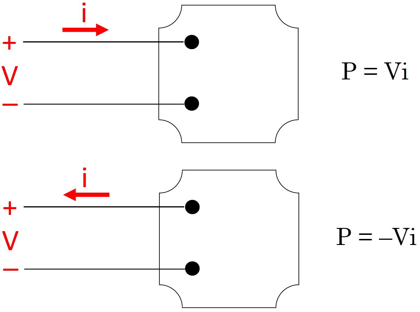
Figure 2 – 2 Power Calculation with Passive Sign Convention
To determine if a circuit element absorbs or delivers power, the sign of the calculated power \color{black}P will be examined. If the calculated power is positive, \color{black}P > 0, it can be concluded that power is absorbed by the element. On the other hand, if \color{black}P \lt 0, the conclusion is the element delivers power.
The total power absorbed in a circuit should balance the total power delivered in the same circuit. Therefore, the aggregate power in a circuit should be zero. This means that the law of conservation of power is obeyed in a circuit.
III. Constant Voltage and Constant Current Modes in DC Power Supply
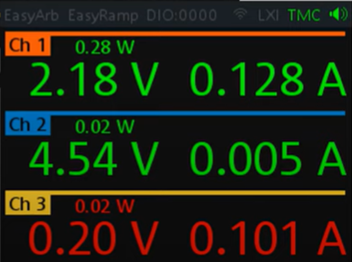
Figure 2 – 3 Channels 1 and 2 in constant voltage mode (green display); channel 3 in constant current mode (red display).
In most cases, the power supply unit operates in the constant voltage mode. In this mode, the unit will output a constant voltage regardless of the load resistance value it sees. The output current is determined by Ohm’s Law V = IR, and depends on the resistance of the connected load. If the load resistance becomes really small, the load will draw a current that can be excessive and large enough to cause damage. To avoid this scenario, the power supply unit should be configured such that the output current is limited to a specific maximum value. This configuration can be performed using the [Current] function on the unit. When the power supply unit outputs a constant current regardless of the configured supply voltage value and the load resistance value, the unit is said to be operating in the constant current mode. Note that the mode of operation is determined by user-specified output current limit. There is no button or menu item to toggle between these two modes.
Hand Analysis
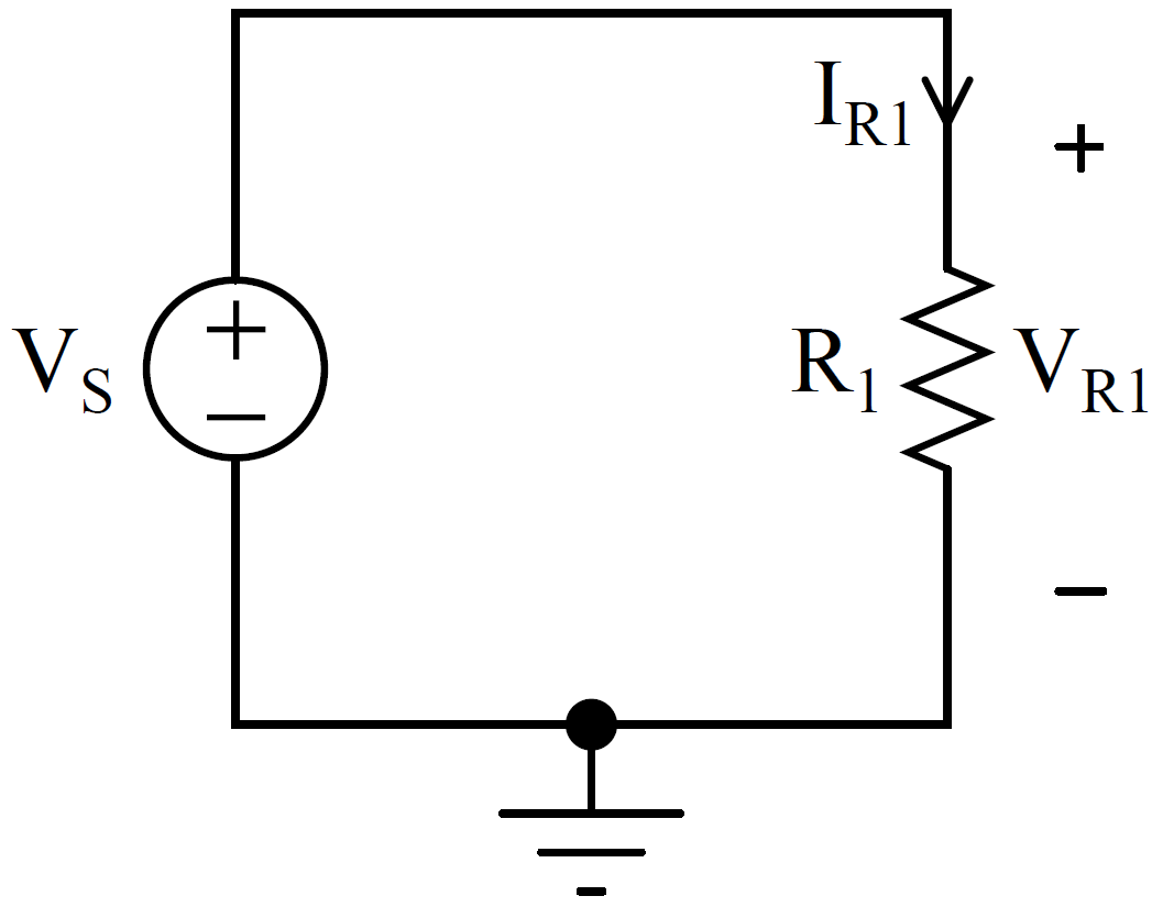
Figure 2 – 4 DC Circuit
For the circuit in Figure 2 – 4, the voltage produced by the source is in the range of \color{black}1V \le V_S \le 10V while the resistor has a resistance in the range of \color{black}1 kΩ \le R_1 \le 10 kΩ. Perform the following steps.
- Choose a value for VS and R1.
- Determine the value for VR1.
- Determine the value for IR1.
- Calculate the power associated with the resistor, PR1. Does the resistor absorb or deliver power?
- Calculate the power associated with the source, PS. Does the source absorb or deliver power?
- Repeat Steps 2 to 5 with at least 4 more different VS values while keeping R1 unchanged.
Simulation
Simulate the circuit in Figure 2 – 4 using a circuit simulator. Determine the values for VR1, IR1, PR1 and PS. Compare all the simulation results with those determined in Hand Analysis.
Hands-on Experiment
Note that all the resistors you are going to use in the lab have a power rating of 0.25W. Please keep this information in mind.
I. Ohm’s Law and Conservation of Energy
Construct the circuit in Figure 2 – 4 using the necessary equipment and tools. Using the same VS and R1 values as in Hand Analysis, perform the following steps.
- Measure VR1 using a DMM.
- Measure IR1 using a DMM.
- Calculate the ratio VR1/IR1 using the measured values. What is the ratio equivalent to?
- Calculate the power associated with the resistor, PR1. Does the resistor absorb or deliver power?
- Calculate the power associated with the source, PS. Does the source absorb or deliver power?
- Is the law of conservation of power/energy obeyed?
- Compile all the data in a table such as Table 1.
- Plot VR1 vs IR1. What is the nature of the plot? Calculate the slope of the plot. What does the slope represent?
- Compare all the measured values with those determined in Hand Analysis and Simulation.
Table 1 Compilation of Data
| VS | VR1 | IR1 | VR1/IR1 | PR1 | PS | |
|---|---|---|---|---|---|---|
| 1. | ||||||
| 2. | ||||||
| 3. | ||||||
| 4. | ||||||
| 5. |
II. Constant Voltage and Constant Current Modes in DC Power Supply
There are two major parts in this section. Both parts use the circuit in Figure 2 – 4.
For the first part, perform the following steps.
- Choose R1 = 1 kΩ.
- Construct the circuit in Figure 2 – 4 using the necessary equipment and tools.
- On the DC Power Supply, set the maximum output current to be 0.2A using the [Current] function.
- Vary VS from 0V to 10V. You can use any reasonable step size such as 1.0V, 0.5V, etc.
- Observe the output voltage of the DC Power Supply. Does it change? What mode is the DC Power Supply operating in?
After completing the 1st part above, turn off the [Output] function on the DC Power Supply.
For the second part, perform the following steps. If you ever smell smoke while going through the process, turn off the DC Power Supply immediately.
- Choose R1 = 10 Ω.
- Construct the circuit in Figure 2 – 4 using the necessary equipment and tools.
- On the DC Power Supply, set the maximum output current to be 0.2A using the [Current] function.
NOTE: You MUST perform this step properly. Also, you MUST ask your ULA to double check the current setting on the power supply unit you are using before proceeding to the next step. - Turn on the [Output] function on the DC Power Supply.
- Vary VS from 0V to 5V. You can use any reasonable step size such as 1.0V, 0.5V, etc.
- Observe the output voltage of the DC Power Supply. Answer the following questions.
- Does it change?
- When does it change? When does it remain unchanged?
- If it remains unchanged, what mode is the power supply operating in?
- If it does change, what mode is the power supply operating in? In this mode, what quantity remains unchanged?
- What are the reasons for both scenarios?
- When the current is 0.2A, what is the power associated with R1? Does this value exceed the power rating?
- When the current is 0.2A, what phenomenon do you observe in the experiment? If you dare, you can touch the resistor with your finger.
Test of Knowledge!
- Plot PR1 vs VR1. What is the nature of the plot?
- Plot PR1 vs IR1. What is the nature of the plot?
- Is the power rating of a resistor important? Why?
- What would happen if the power absorbed by a resistor exceeds its power rating?
- When do you think you need to change the current setting on a power supply?
- Why is ammeter connected in series?
- Why is voltmeter connected in parallel?