Objectives
- To verify Kirchhoff’s Laws experimentally.
- To analyze circuit with components connected in series and parallel.
- To understand the concepts of open and short circuits.
- To familiarize with taking voltage and current measurements using a DMM.
Equipment
- Breadboard
- DC Power Supply
- Digital Multimeter (DMM)
Background
I. Kirchhoff’s Voltage Law (KVL)
Kirchhoff’s Voltage Law (KVL) states that the algebraic sum of all the voltages around any closed path or loop in a circuit equals to zero.
II. Kirchhoff’s Current Law (KCL)
Kirchhoff’s Current Law (KCL) states the algebraic sum of all the currents entering or leaving a node in a circuit equals to zero. In other words, the sum of all currents flowing into a node is equal to the sum of all currents flowing out of the node.
Hand Analysis
There is no hand analysis in this experiment.
Simulation
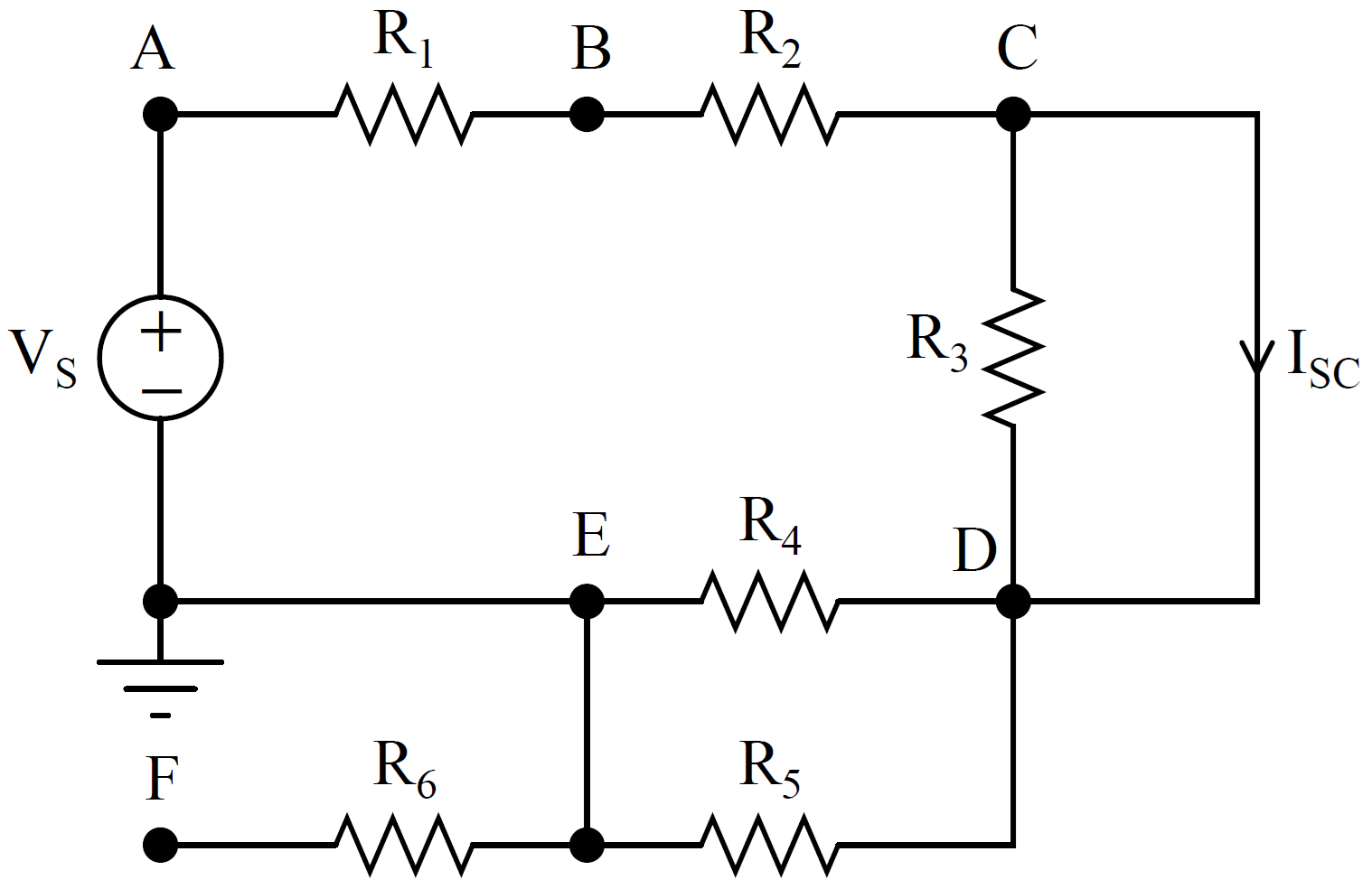
Figure 3 – 1 DC Circuit
For the circuit in Figure 3 – 1, use the following settings.
- Configure the supply voltage to be VS = 5V.
- Choose any resistor values within the range of 1 kΩ to 30 kΩ. Assign the same value to all resistors with the same name and different values to those with different names. Consider the availability of resistors in the lab while choosing the values.
- Denote the voltage between nodes ‘X’ and ‘Y’ as VXY, where the 1st subscript ‘X’ represents the positive polarity while the 2nd subscript ‘Y’ represents the negative polarity.
Simulate the circuit in Figure 3 – 1 using a circuit simulator. Using the required tools/functions in the circuit simulator, measure the following voltages and currents. For each current, pick a desired direction.
- VAB, VBC, VCD, VDE, VEF and VEA
- VAC, VAD, and VCE
- IR1, IR2, IR3, IR4, IR5, IR6, IVS, and ISC
Hands-on Experiment
Construct the circuit in Figure 3 – 1 using the necessary equipment and tools. Perform the following steps.
- Using the DMM, measure all the voltages and currents mentioned in Simulation.
- Compare all the measured values with those determined in Simulation.
I. Kirchhoff’s Voltage Law (KVL)
Using the measured values obtained from DMM, perform the following steps.
- Write a KVL equation for all the following loops. Write each equation using the necessary variables first before substituting the measured values into the equation.
- A —> B —> C —> D —> E —> A
- A —> B —> C DIRECTLY to A
- E DIRECTLY to C —> B —> A —> E
- D —> C DIRECTLY to E —> D
- Combine KVL equations (3) and (4) algebraically into one equation. What observations can you make from this new equation?
- Do all the above equations satisfy KVL?
- Write a KVL equation that involves VAD.
- Can you write more KVL equations for other loops?
II. Kirchhoff’s Current Law (KCL)
Using the measured values obtained from DMM, perform the following steps.
- Write a KCL equation for nodes A, B, C, D, and E. Write each equation using the necessary variables first before substituting the measured values into the equation.
- Do all the above equations satisfy KCL?
III. Series and Parallel Connections
Using the measured values obtained from DMM, answer the following questions.
- In the circuit in Figure 3 – 1, are there components connected in series? If so, point out all the series connections and the corresponding components.
- What measured values do you use to verify the series connections?
- In the circuit in Figure 3 – 1, are there components connected in parallel? If so, point out all the parallel connections and the corresponding components.
- What measured values do you use to verify the parallel connections?
IV. Open and Short Circuits
Using the measured values obtained from DMM, answer the following questions.
- What is the value for IR6? Why?
- What is the value for VEF? Why?
- What is the value for the voltage across R3? Why?
- What is the value for IR3? Why?
- What is the value for ISC? Why?
- What would IR2 do after it has reached node ‘C’? Would IR2 split? Why?
- Is there an open circuit in Figure 3 – 1? If so, where is it?
- Is there a short circuit in Figure 3 – 1? If so, where is it?
Test of Knowledge!
- How many KVL equations can you write for any given circuit?
- How many KCL equations can you write for any given circuit?
- Is KVL based on conservation of energy or conservation of charge?
- Is KCL based on conservation of energy or conservation of charge?
- When you are writing a KVL equation, does it matter if you follow the clockwise or the counterclockwise direction?
- What type of connection will yield the same voltage across multiple components?
- What type of connection will yield the same current through multiple components?
- Under what conditions will an open circuit appear in a circuit?
- Under what conditions will a short circuit appear in a circuit?