Objectives
- To understand the concept of equivalent resistance.
- To understand the effects of open and short circuits on equivalent resistance.
- To familiarize with measuring equivalent resistance using a DMM.
Equipment
- Breadboard
- Digital Multimeter (DMM)
Background
I. Equivalent Resistance
Many students do not grasp the basic principle or the big picture of equivalent resistance. Hopefully, by the end of this experiment, you will acquire a deep understanding of equivalent resistance and be able to answer the following questions with full clarity.
- What is equivalent resistance?
- Is equivalent resistance all about combining resistors connected in series and parallel?
- Is combining resistors connected in series just a special case of equivalent resistance?
- Is combining resistors connected in parallel just a special case of equivalent resistance?
- Can you still find the equivalent resistance between any two nodes of a circuit if the circuit has no resistor connected in series or parallel or even worse, the circuit does not contain any resistor?
- What are the effects of open and short circuits on equivalent resistance?
II. Equivalent Resistance Measurement
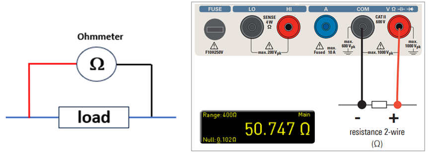
Figure 4 – 1 Resistance Measurement
Similar to voltage measurement, equivalent resistance is measured by connecting the DMM in parallel with the device under test (DUT), as shown in Figure 4 – 1. On the DMM, the red probe should be connected to the V-Ω port while the black probe should be connected to the COM port. Also, press the [Ω] button on the front panel to configure the DMM for resistance measurement.
Hand Analysis
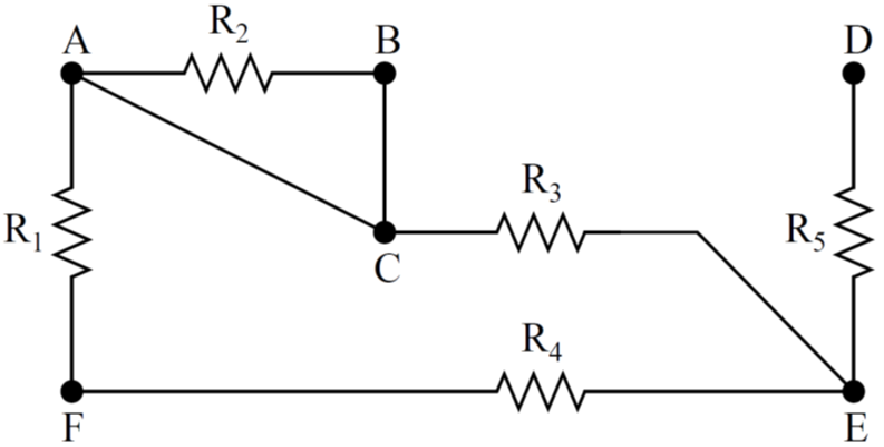
Figure 4 – 2 Circuit of Interest
For the circuit in Figure 4 – 2, choose any resistor values within the range of 1 kΩ to 30 kΩ unless specified otherwise. Assign the same value to all resistors with the same name and different values to those with different names. Determine the equivalent resistance between
- nodes A & F, RAF;
- nodes B & F, RBF;
- nodes A & B, RAB;
- nodes A & D, RAD;
- nodes A & E, RAE;
- nodes B & E, RBE;
- nodes D & E, RDE;
- nodes D & F, RDF;
Hands-on Experiment
Prior to constructing the circuit in Figure 4 – 2 on a breadboard, measure the individual resistance for all 5 resistors using a DMM. Compare the nominal value with the measured value. Note that the nominal value of a resistor can be obtained by deciphering its color bands.
Construct the circuit in Figure 4 – 2 on a breadboard. Perform the following steps.
- Measure the equivalent resistance for all cases specified in Hand Analysis.
- Compare all measured values with those determined in Hand Analysis.
Perform the following steps using TWO DMMs.
- Measure the equivalent resistance RAF again using one DMM.
- With one DMM measuring the equivalent resistance RAF, use a second DMM to measure the current flowing from the first DMM to either node A or F. This current, denoted as IT, is the current supplied by the first DMM to the circuit.
- With one DMM measuring the equivalent resistance RAF, use a second DMM to measure the voltage between nodes A and F. This voltage, denoted as VT, results from the supplied current flowing through the circuit.
- Compute the value for VT/IT, which is the ratio of the measured voltage obtained in Part B to the measured current obtained in Part A. What is this ratio equal to?
- With one DMM measuring the equivalent resistance RAF, use a second DMM to measure IR2, which is the current through R2.
- Is IR2 = 0 or insignificant compared to IT? If so, should R2 be included in or excluded from RAF?
- With one DMM measuring the equivalent resistance RAF, use a second DMM to measure IR5, which is the current through R5.
- Is IR5 = 0 or insignificant compared to IT? If so, should R5 be included in or excluded from RAF?
- What is the complete path of flow for the supplied current IT?
- Measure the equivalent resistance RDE again using one DMM.
- With one DMM measuring the equivalent resistance RDE, use a second DMM to measure the supplied current IT.
- With one DMM measuring the equivalent resistance RDE, use a second DMM to measure the resulting voltage VT.
- Compute the value for VT/IT. What is this ratio equal to?
- With one DMM measuring the equivalent resistance RDE, use a second DMM to measure IR1, IR2, IR3, and IR4.
- Are all four currents zero or insignificant compared to IT? If so, should all four corresponding resistors be included in or excluded from RDE?
- What is the complete path of flow for the supplied current IT?
- Measure the equivalent resistance RAB again using one DMM.
- With one DMM measuring the equivalent resistance RAB, use a second DMM to measure the supplied current IT.
- With one DMM measuring the equivalent resistance RAB, use a second DMM to measure the resulting voltage VT.
- Compute the value for VT/IT. What is this ratio equal to?
- With one DMM measuring the equivalent resistance RAB, use a second DMM to measure IR1, IR2, IR3, IR4, and IR5.
- Are all five currents zero or insignificant compared to IT? If so, should all five resistors be included in or excluded from RAB?
- What is the complete path of flow for the supplied current IT?
- Grab any inductor in the lab and measure its resistance using a DMM. Since the circuit of interest contains an inductor only and no resistor, is the equivalent resistance zero?
- In essence, what is equivalent resistance?
Simulation
Construct the circuit in Figure 4 – 2 in a circuit simulator. Measure the equivalent resistance for all cases specified in Hand Analysis. Compare all simulation results with those determined in Hand Analysis and Hands-on Experiment.
NOTE: LTSpice does not provide a tool or built-in function that facilitates the direct measurement of equivalent resistance. What should you do then? Cry?
NOTE: If you cannot complete all the simulation assignment during the lab session, you can complete them at home.
Test of Knowledge!
- Answer all the questions posed in Background.
- How does a DMM make a resistance measurement?
- What is equivalent resistance? What is equivalent resistance? What is equivalent resistance? ……