Objectives
The ultimate goal of the project is to determine the Thevenin/Norton equivalent circuit of any given DC circuit experimentally.
Tools
- Lab Equipment
- Circuit Simulator
- Hantek 3-in-1 Digital Equipment
- Powered Breadboard
Assessment
The overall weighted grading scheme is as follows:
Table 1 Overall Weighted Grading Scheme
| Category | Percent of Overall Grade |
|---|---|
| Demo | 70% |
| Report | 30% |
| Total | 100% |
I. On-the-spot Demo
At the start of a lab session, each group will be given a randomly chosen circuit diagram. An example of a circuit diagram is shown in Figure 1. All groups are required to complete the following tasks by the end of a lab session.
- Determine the Thevenin/Norton equivalent circuit of the given circuit using a circuit simulator.
- Determine the Thevenin/Norton equivalent circuit of the given circuit experimentally using the available equipment in the laboratory.
- Demonstrate both simulation and experimental results on the spot to your Lab TA. Provide detailed explanations and reasonings on how you have obtained the results during your demo.
- Record down your results for the writing of your report.
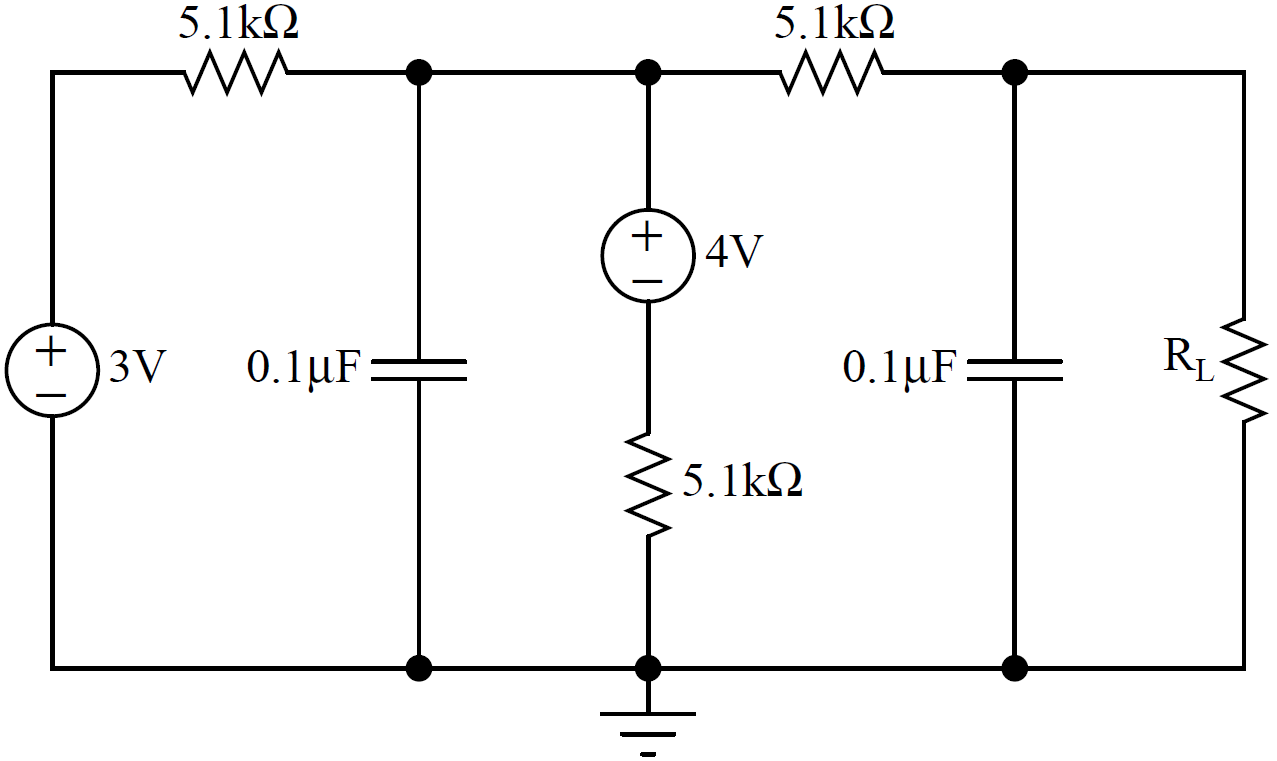
Figure 1 Sample DC Circuit
The grades earned in this first category of assessment depend highly on your ability to complete the above tasks. The weighted grading scheme is as follows:
Table 2 Weighted Grading Scheme for Demo
| Category | Percent of Overall Grade |
|---|---|
| Simulation Results and Achievement | 15% |
| Simulation Demonstration and Elaboration | 5% |
| Experimental Results and Achievement | 35% |
| Experimental Demonstration and Elaboration | 15% |
| Total | 70% |
IMPORTANT NOTES:
- The circuit diagram for your project will only be revealed to you at the start of a lab session. To prepare fully for your project execution and demonstration, you are highly encouraged to perform circuit simulations and experiments at home so that you can figure out and get familiar with the required implementation for your project. To perform experiments outside of the laboratory, you can loan out a Hantek 3-in-1 digital equipment and a powered breadboard. You can also acquire circuit components from the laboratory, and they are not required to be returned.
- Collaborations between any groups are strictly prohibited during a lab session.
- All project demonstrations must be performed during a lab session. No project demonstration can be performed outside lab session.
II. Report
Document all your analysis, results and findings in a report. The content of your report should include, but not limited to, the following sections.
- Objectives and Tasks – define and outline explicitly the objectives and tasks
- Dissection of Implementation – present your implementation in a detailed, part-by-part analysis
- Simulation Results – present your simulation results with clarity
– include screenshots of simulated circuits, results, etc.
- Experimental Results – present your experimental results with clarity
– include oscilloscope figures, screenshots of DMM measurements, etc.
- Results Comparison – compare simulation and experimental results
– explain discrepancies pertaining to concepts
- Conclusions
The weighted grading scheme is as follows:
Table 3 Weighted Grading Scheme for Report
| Category | Percent of Overall Grade |
|---|---|
| Objectives and Tasks | 2.5% |
| Dissection of Implementation | 10.0% |
| Simulation Results | 5.0% |
| Experimental Results | 5.0% |
| Results Comparison | 5.0% |
| Conclusions | 2.5% |
| Total | 30% |