Skip to content
EEL 3123 Linear Circuits II Lab Manual
  • Introduction
    • Safety Rules & Operating Procedures
    • Laboratory Safety Information
    • Troubleshooting Hints
  • Experiments
    • #1: DC Measurements
    • #2: Circuit Analysis Techniques
    • #3: AC Measurements
    • #4: First and Second Order Circuits
  • Projects
    • Project #1 Thevenin’s Theorem
    • Project #2 Circuit Design #1
      • Circuit Design Part A
      • Circuit Design Part B
      • Circuit Design Part C
    • Project #3 AC Load Measurement
    • Project #4 Circuit Element Identification
    • Project #5 Circuit Design #2
  • Appendix
    • I. Lab Component
    • II. List of Available Resistors & Capacitors
    • III. Standard Resistor Color Code

Circuit Design Part A

In this first part, the goal is to design two circuits that meet certain design requirements under certain design constraints.

Figure 1 Circuit Design Part A
Design Requirement
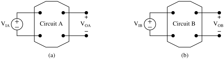
  1. Referring to Figure 1 (a), design Circuit A such that VOA = KA×VIA, where VIA and VOA are the input and output voltages respectively.
  2. Referring to Figure 1 (b), design Circuit B such that VOB = KB×VIB, where VIB and VOB are the input and output voltages respectively.
  3. The values for KA and KB are provided in Table 2.

Table 2     Design Specifications

Lab SectionDesign Specification
EEL 3123C-11KA = 0.6 and KB = 0.5
EEL 3123C-12KA = 0.75 and KB = 0.6
EEL 3123C-13KA = 0.5 and KB = 0.9
EEL 3123C-14KA = 0.9 and KB = 0.8
EEL 3123C-15KA = 0.8 and KB = 0.75
EEL 3123C-16KA = 0.8 and KB = 0.9
Design Constraint
  1. You are allowed to use resistors with resistances within the range of 1 kΩ to 10 kΩ only. Refer to APPENDIX II for available resistors.
  2. Use as FEWEST components as possible.

Table of Contents

  • Introduction
    • Safety Rules & Operating Procedures
    • Laboratory Safety Information
    • Troubleshooting Hints
  • Experiments
    • #1: DC Measurements
    • #2: Circuit Analysis Techniques
    • #3: AC Measurements
    • #4: First and Second Order Circuits
  • Projects
    • Project #1 Thevenin’s Theorem
    • Project #2 Circuit Design #1
    • Circuit Design Part A
    • Circuit Design Part B
    • Circuit Design Part C
    • Project #3 AC Load Measurement
    • Project #4 Circuit Element Identification
    • Project #5 Circuit Design #2
  • Appendix
    • I. Lab Component
    • II. List of Available Resistors & Capacitors
    • III. Standard Resistor Color Code

About

Lab Manual Authors:
Dr. Parveen Wahid
Ms. Ya Shen
Dr. Chung Yong Chan

Project Assistant Producers:
Ethan Partidas
Mena Mishriky                                              Ethan Fluhr                                            Isaiah McCarty

Webmasters:
Brandon Cuevas
Garett Goodale

For questions and revision requests, please contact Chung Yong Chan at chungyong.chan@ucf.edu.

Revised March 2023

Theme by Colorlib Powered by WordPress